|
The Feasibility Study (FS) report (AECOM 2014) for sediments in Pearl Harbor identified principally mercury and total PCBs as chemicals of concern at multiple under pier locations, including the Sierra 1 Pier. The Sierra 1 is an active submarine berthing area, with limited access to the under-pier sediments. Under-pier structures consist of concrete piles and beams that support the pier deck, and utility conduit and piping to supply power, potable water, saltwater, and compressed air, and to remove bilge water and sanitary waste. Concrete beams (pile caps) run perpendicular from the bulkhead and are spaced apart 10 feet on center. Each beam is supported by four concrete piles spaced 12 feet, 4 inches center to center.
Because of the contaminant levels and the relatively moderate bottom slope Sierra 1B was considered a suitable site to evaluate the constructability and effectiveness of amendment application as a potential remedial alternative for contaminated sediments requiring remediation in Pearl Harbor.
Treatability Studies
The average TOC in the Sierra Pier 1 sediment is 2.5% with an average reported grain size in the TS Work Plan of 66% (42.5 – 96%) silts and clay size particles. The target addition of AC was set at 2.5% by weight to achieve a final total carbon (TOC +AC) of approximately 5%. The target load was not based on any ex situ testing, but on previous work in part done under the SERDP/ESTCP program (Ghosh et al. 2008, 2011).
The target application rates are presented in the TS Design report as 0.8 inches (16,500 lbs) of SediMite and 3.75 inches (120,000 lbs) of AquaGate+PAC over the respective 44 x 100 ft test areas. The difference in application thickness/amendment weight is due to the lighter SediMite having a higher AC content (45% AC by weight and a dry bulk density of 45 lbs/ft3) as compared to the AquaGate + PAC™ (5% AC by weight and a dry bulk density of 85 - 90 lbs/ft3).
For both products, considerable shipping expense was incurred as the formulations came from the mainland U.S. Both manufacturers have discussed the possibility of formulating the material in Hawaii should full-scale remediation using AC be applied.
Engineering Specifications and Contracting
AECOM provided the construction oversite while the actual construction work was completed Sea-Engineering of Oahu. The TS Design document served as the basis of the design and bid.
Placement Methods
Sediment located directly under Sierra Pier required that material be distributed through the fire suppression ports within the pier (click here to view figure). Placement occurred using a combination of pneumatic conveyance and gravity feed. The equipment used for the TS was custom built for this purpose (see below for specifics).
The application rates of both materials depended on several factors. Air pressure, material flow rate, rate of hopper being filled, water pressure, and dust levels were all considered and adjusted over the course of the project to optimize the delivery. In part due to the configuration of the under dock support pilings, amendment placement occurred in 10 x 10 ft cells: 40 per treatment (click here to view figure). Turbidity control was was managed by placing a silt curtain around the entire application area. The applied AC principally had settled out of the water column within 4 hours application, and by 8 hours the clarity within and outside the turbidity curtain as the same.
SediMite Placement
For SediMite a steel hopper was designed and constructed to hold approximately 300 lbs of material; sufficient to treat one 10 ft × 10 ft cell. The hopper was approximately 5 feet tall to allow for material access and to allow space for the under-hopper equipment. A specially fabricated PVC gate valve was installed below the hopper to regulate the amount of amendment material gravity-feeding from the hopper. A compressed air fitting was attached beneath the gate valve to convey material through the hose for placement below the pier deck. The compressed air nozzle was designed to direct and push air down the tube, away from the hopper.
A 4 inch diameter, semi-rigid, cam-lock hose was connected below the compressed air input. This hose also was fitted with a welded, multi-jet water spray nozzle and water line, to wet the material as it exited the hose. This was necessary to limit dust created below the pier deck. A two person, under-deck crew worked off small, 4 foot by 8 foot work floats to place the material conveyed from the on-deck hopper. The cycle time for each of the 100 ft2 cells was approximately 10 minutes.
Early in the application it became apparent that the under-dock dust created by aerially broadcasting the SediMite created a hazardous (potentially explosive) condition. Placement was adjusted so that the under-deck crew placed material by direct under-water
application.
AquaBloc+PAC Placement
The delivery equipment and crew was the same as described for SediMite application above. For each cell 2,660 lbs of AquaGate+PAC was applied to provide a 3.75 inch layer of material. AquaGate+PAC was delivered to the site in 2,500 lb bulk bags. Material was broadcast uniformly over each treatment cell. Thus one entire bulk bag, plus an additional 160 lbs. of material (approximately three 5-gallon buckets full) were placed in each cell. The delivery hose with the nozzle that had multiple water spray jets for dust suppression was used, but it was not necessary to dispense the material underwater for dust control as was the case for SediMite. The cycle time for each cell was approximately 30 minutes.
Placement Verification
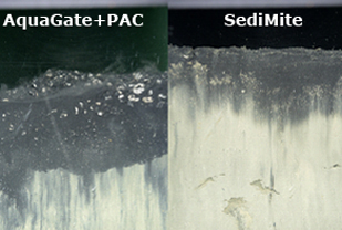
The design criteria for SediMite and AquaGate+PAC application were minimum thickness of 0.8 inches and 3.75 inches, respectively. To assess the efficacy of the placement method the following measures were used during, and post-application: diver inspections, sediment thickness gauges, weighted buckets, sediment push cores, and SPI. No amendment was observed in the control plot.
SediMite application verifications average approximately 1 inches of SediMite in the test area. During application the subcontractor was asked to place around 1 inches of SediMite; 0.8 inches application was considered to be a tolerance that was overly restrictive. The SPI results for individual plots indicate variations in placement ranging between 0.12 inches and 3.22 inches for SediMite. This could have been caused by differences in topography for the measured location or application non-uniformity for that spot. However, majority of the locations for SPI indicate adequate or over application of amendment and the average thickness for SediMite in Plot A is around 1.04 inches. (Click here to view video of the post-verification transect for SediMite).
The SPI results for AquaGate+PAC indicates an average thickness of 3.02 inches of material was placed. The other measures indicate a range of thickness of 3.66 to 5.254.51 inches of place material. (Click here to view video of the diver post-verification transect for AquaGate).
Performance Monitoring
Monitoring of the project is being done with a baseline (pre-construction), and at 6, 12 and 18 months post-placement. The first post-placement monitoring was done in August, 2015. Monitoring tools at the site include diver video surveys, SPI, bulk sediment and porewater measures of PCBs and metals, TOC and black carbon measures, ex-situ bioaccumulation studies with Macoma, and benthic community surveys. As survey results become available they will be posted at this website.
Costs
Construction costs will be posted as they become available.
|