|
Prior laboratory studies and a pilot test project conducted under ESTCP project ER-1207 in the intertidal sediments at HPNS demonstrated the efficacy of using AC as an amendment for sequestration of PCBs. The 2015 AC placement is intended to demonstrate the efficacy of placement and PCB sequestration on a larger scale (1 acre). The 1-acre test area was split into two a halves (one north and one south, each with both intertidal and subtidal components) with each half demonstrating a different type of amendment: AquaGate + PACTM and SediMiteTM (click here to view figure).
Treatability Studies
Treatability studies were conducted by Dr. Richard Luthy of Stanford University under three SERDP/ESTCP projects (Table 1). Based upon those previous studies the material specifications for the AC were detailed in the Work Plan for the Demonstration of Activated Carbon Amendments at HPNS (click here to view the Work Plan).
AquaGate+PACTM
- Activated carbon by weight: 10 percent
- Dry Bulk Density: 60 to 70 pounds per cubic foot
- Placement of AquaGate+PAC™ included a 10 percent contingency amount (for anticipated losses); approximately 10.3 pounds per square foot, or 1.9 inches thick.
SediMite
- Activated carbon by weight: 40 percent
- Dry Bulk Density: 45 to 55 pounds per cubic foot
- Placement of SediMite included a 25 percent contingency amount (for anticipated losses); approximately 3 pounds per square foot, or 0.8 inches thick
EPA expressed concern during review of the Work Plan was that the limestone core typically used by AquaGate might alter the sediment pH, adversely affecting the benthic organisms. AquaGate then modified the product to use pea gravel as the base material.
Engineering Specifications and Contracting
To be completed.
Placement Methods
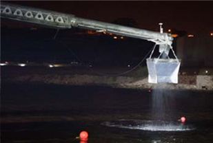
A telebelt truck with a 130 foot reach, mounted on board a 120 foot by 40 foot spud barge was
used for placement of the AC. The barge was held in place by spuds during placement; an auxiliary tug maneuvered the barge between placement positions. Supporting the telebelt, a small 16-ton excavator, with bucket removed and equipped with a lifting shackle, was used to supply super sacks, weighing approximately 2,200 lbs. each, to the telebelt’s feed hopper.
The telebelt was equipped with a custom fabricated shroud at the belt discharge which allowed the media to be vertically released onto an approximate area of X by X ft. Tracking of amendment placement was accomplished using a DGPS mounted above the discharge end of the telebelt's boom, with the area marked by two buoys within which the operator maneuvered the shroud. The positioning information was continuously transmitted to onboard to a navigation and position monitoring system that would inform the operator of the horizontal position and track lines to ensure there were no gaps in coverage.
Open water placement of amendment was accomplished by extending the telebelt boom approximately 60’ off the end of the barge and spreading the amendment in a zigzag arc pattern across the 65’ width of the test area. The boom radius was decreased by
approximately 2 ft at the end of each swing. Application rate for the AquaBlock was approximately XX pounds for every N swings across the target area. The application rate for SediMite was approximately XXX lbs per swing across the target area.
Once the telebelt boom radius was decreased during the placement pattern, such that the telebelt could no longer efficiently reach lateral extents of the placement area, the spud barge was relocated to the next placement position and the process repeated.
The total volume of AC delivered was less than anticipated, so the area of each of the test plots was adjusted to maintain the specified depth of AC. Of the overall 1 acre test area, AquaGate+PAC was placed over 17,850 ft2 (85 x 210 ft) to a depth of NN inches, while the SediMite was spread out over 16,800 ft2 (80 x 210 ft) to a depth of NN inches. This left a buffer area of approximately 9,450 ft2 (45 x 210 ft) between the two test plots. (click here to view figure) Total placement of AquaBlock+PACTM and SediMiteTM over the test area was (X lbs) and
XXX lbs, respectively.
Cover thickness during placement was verified using 2 ft x 2 ft x 1 ft settling pans placed on the bottom of the test area. Two pans per every 5,000 ft2 were deployed, weighted down to hold in place, and fixed with cables on buoys for retrieval. After placement coverage was completed by the telebelt operator, the pans were retrieved to verify that the target thickness was achieved.
Performance Monitoring
Pre- and post-placement monitoring includes
- Sediment Profile Imaging
- Hydrodynamic monitoring of tides, currents and waves
- Bulk sediment core and grab samples of PCBs, TOC, black carbon and grain size
- Passive Samplers (SPME) for PCB congeners
- Benthic community analyses
As of this posting, the pre-placement, and the construction-placement monitoring were completed, but those reports were not yet available. This site will be updated as those reports are released.
Costs
Costs were not available at the time of posting. This page will be updated as those become available.
|